Das Intervall zwischen der ersten Kalibrierung und der Neukalibrierung hängt von mehreren Faktoren ab, einschließlich der Betriebstemperatur des Sensors, der Luftfeuchtigkeit, den Druckbedingungen, den Arten von Gasen, denen er ausgesetzt ist, und der Dauer der Aussetzung.
Das Maß der Variation der Kreuzstörung kann erheblich sein. Dies wird anhand von Tests einer begrenzten Anzahl von Sensoren bewertet, die auf nicht-zielgerichtete Gase statt auf die Zielgase selbst reagieren. Es ist wichtig zu beachten, dass bei Änderungen der Umgebungsbedingungen sich die Sensorleistung unterscheiden kann und die Werte der Kreuzstörung zwischen verschiedenen Sensorbatchs um bis zu 50 % variieren können. Daher sollten diese Variablen in praktischen Anwendungen für Genauigkeit und Zuverlässigkeit des Sensors vollständig berücksichtigt werden.
Die Verwendung einer Pumpe beschleunigt die eigene Reaktionsrate des Sensors nicht, aber sie kann Gasproben schnell und effizient aus schwer zugänglichen Positionen durch den Sensor ziehen. Dadurch kann die Pumpe die Gesamtreaktionszeit des Geräts beeinflussen.
Ein Film oder Filter kann vor dem Sensor zur Schutzpositioniert werden, aber er muss sicherstellen, dass keine "Tote Zone" entsteht, die die Reaktionszeit des Sensors verlängern könnte.
Beim Entwerfen eines Probenahmesystems ist es entscheidend, Materialien zu verwenden, die verhindern, dass Gase an den Oberflächen des Systems adsorbiert werden. Die besten Materialien umfassen Polymere, PTFE, TFE und FEP. Eine Gas-Konzentration kann zu Feuchtigkeitskondensation führen, was den Sensor blockieren oder zu Überlauf führen kann, daher sollten angemessene Dehydratoren verwendet werden – wie Nafion-Schläuche, um Feuchtigkeit in der Kondensationsphase zu entfernen. Bei Hochtemperaturgasen sollte das Proben-Gas abgekühlt werden, um den Temperaturanforderungen des Sensors gerecht zu werden, und entsprechende Filter sollten verwendet werden, um partikelförmige Stoffe zu entfernen. Darüber hinaus können axiale chemische Filter im Probenahmesystem installiert werden, um Querinterferenzen durch Gase zu beseitigen.
Die eigene Temperatur des Sensors bestimmt dessen Minimalanzeigestrom, und die Temperatur des gemessenen Gasproben hat einen gewissen Einfluss darauf. Die Rate, mit der Gasmoleküle durch die Poren zum Messelektroden gelangen, bestimmt das Signal des Sensors. Wenn die Temperatur des durch die Poren diffundierenden Gases sich von der Temperatur des Gases innerhalb des Sensors unterscheidet, kann dies die Sensitivität des Sensors in gewissem Maße beeinflussen. Es können leichte Drifts oder vorübergehende Stromänderungen auftreten, bevor das Gerät vollständig eingerichtet ist.
Sauerstoffsensoren können kontinuierlich Sauerstoffkonzentrationen im Bereich von 0–30 % nach Volumen oder Partialdrücke im Bereich von 0–100 % nach Volumen überwachen. Toxische Gassensoren werden typischerweise für intermittierende Überwachung von Zielgasen verwendet und sind nicht für eine Dauermessung geeignet, insbesondere in Umgebungen mit hohen Konzentrationen, hoher Luftfeuchtigkeit oder hohen Temperaturen. Um eine kontinuierliche Überwachung zu erreichen, wird manchmal eine Methode eingesetzt, bei der zwei (oder sogar drei) Sensoren abwechselnd genutzt werden, sodass jeder Sensor maximal die Hälfte der Zeit dem Gas ausgesetzt ist und sich während der anderen Hälfte in frischer Luft regenerieren kann.
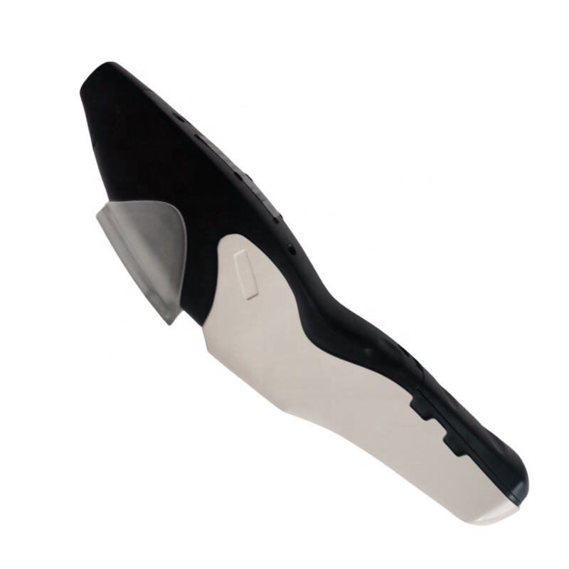
Wir verwenden verschiedene Kunststoffmaterialien unter Berücksichtigung der Verträglichkeit mit dem internen Elektrodesystem und den Anforderungen an die Anwendungsbeständigkeit. Häufig verwendete Materialien umfassen ABS, Polycarbonatfasern oder Polypropylen. Weitere detaillierte Informationen finden Sie im Datenblatt jedes Sensors.
Obwohl es kein Zertifikat gibt, das seine intrinsische Sicherheit beweist, kann das Produkt stabil den Anforderungen an die interne Sicherheit gerecht werden.
Dreielektroden- und Vier_elektroden_sensoren eignen sich zur Verwendung in einer speziellen Schaltung namens Potentiostat. Der Zweck dieser Schaltung ist es, das Potential des Mess_elektroden (und Hilfs_elektrode) im Bezug auf die Gegen_elektrode zu kontrollieren, während sie den fließenden Strom verstärkt. Die Schaltung kann mit der folgenden einfachen Methode getestet werden:
• Entfernen Sie den Sensor.
• Verbinden Sie das Gegen_terminal mit seinem entsprechenden Terminal in der Schaltung.
• Messen Sie das Potenzial des Sensorterminals (und des Hilfs-terminals). Bei einem nicht polarisierten Sensor sollte das Testergebnis 0 sein (±1mV), was dem empfohlenen Offsetspannung für einen polarisierten Sensor entspricht.
• Verbinden Sie das Sensorterminal (oder Hilfsterminal) mit der Schaltung, um die Ausgangsspannung zu erhalten.
Die oben genannten Schritte können in den meisten Fällen bestätigen, dass die Schaltung normal funktioniert. Nach dem Austausch und erneuten Fixieren des Sensors sollte die Spannung zwischen dem Sensorterminal und dem Referenzterminal eines nicht polarisierten Sensors weiterhin null sein oder dem empfohlenen Offsetspannung eines polarisierten Sensors entsprechen.
In den meisten Fällen können die oben genannten Schritte bestätigen, dass die Schaltung normal funktioniert. Nach dem Austausch und erneuten Fixieren des Sensors sollte die Spannung zwischen den Sensorelektroden und dem Referenzelektroden eines nicht polarisierten Sensors nahe null liegen oder dem empfohlenen Offsetspannung eines polarisierten Sensors entsprechen.
Allgemein ly, Sensoren können in einem typischen Reinigungssystem nicht gereinigt werden, ohne irreparable Schäden anzurichten oder ihre Überwachungsleistung zu beeinträchtigen. Hoher Druck und Temperatur werden ihr Dichtung beschädigen, und aktive Chemikalien wie Ethenoxid und Wasserstoffperoxid können den Elektrokatalysator zerstören.
In Bezug auf den Mechanismus ist eine niedrige Temperatur im Allgemeinen kein großes Problem. Das flüssige Elektrolyt in allen Sensoren (außer Sauerstoffsensoren) friert erst bei Temperaturen um -70°C ein. Längere Belastung mit extrem niedrigen Temperaturen kann jedoch die Befestigung der Kunststoffgehäuse am Gestell beeinträchtigen.
Bei Sauerstoffsensoren bedeutet hoher Salzgehalt zwar, dass sie nicht sofort beschädigt werden, aber das Elektrolyt des Sauerstoffsensors friert bei ungefähr -25 bis -30°C ein, was letztendlich zu einem Sensorversagen führen kann.
Temperaturen über dem oberen Grenzwert werden Druck auf das Dichtungssystem des Sensors ausüben und letztendlich zu einem Elektrolyt-Durchfluss führen. Die zur Herstellung der meisten Sensoren verwendeten Kunststoffe weichen ab, sobald die Temperatur 70°C überschreitet, was rasch zum Ausfall des Sensors führt.
Alle Sensoren verwenden ähnliche Dichtungssysteme, bei denen die hydrophoben Eigenschaften von PTFE-Materialien verhindern, dass Flüssigkeit aus dem Sensor austritt (auch bei Lüftungsöffnungen). Wenn der am Sensoranschluss angelegte Druck plötzlich über die zulässigen internen Grenzwerte hinaus ansteigt oder abfällt, können Membran und Dichtung des Sensors verformt werden, was zu Leckagen führen kann. Wenn sich der Druck langsam genug ändert, kann der Sensor möglicherweise außerhalb der Drucktoleranz arbeiten, aber konsultieren Sie zur Beratung den technischen Support.
Sensoren, die in ihrer Originalverpackung aufbewahrt werden, verschlechtern sich normalerweise selbst über den Haltbarkeitszeitraum hinaus nicht erheblich. Für eine langfristige Lagerung empfehlen wir, heiße Umgebungen zu vermeiden, wie Fenster, die direktem Sonnenlicht ausgesetzt sind.
Wenn Sensoren aus ihrer Originalverpackung entfernt werden, halten Sie sie an einem sauberen Ort und vermeiden Sie Kontakt mit Lösungsmitteln oder starkem Rauch, da Rauch in die Elektroden aufgenommen werden kann, was zu Funktionsstörungen führen kann. Sauerstoffsensoren sind eine Ausnahme: Sobald sie installiert sind, beginnen sie, verbraucht zu werden. Deshalb werden sie während des Transports oder der Lagerung in versiegelten Verpackungen bei reduzierten Sauerstoffkonzentrationen gelagert.
Zweielektroden-Sensoren, wie Sauerstoffsensoren und Zweielektroden-Kohlenmonoxid-Sensoren, erzeugen elektrische Signale durch chemische Reaktionen und benötigen keine externe Energiequelle. Drei- und Vier_elektroden_Sensoren jedoch müssen einen Potentiostaten-Schaltkreis verwenden und benötigen daher eine Stromversorgung. Tatsächlich benötigt der Sensor selbst weiterhin keine Energie, da er durch Oxidation oder Reduktion des Zielgases direkt einen Ausgangsstrom erzeugt, aber der Schaltkreisverstärker verbraucht einige Strom – obwohl dieser auf sehr niedrige Werte reduziert werden kann, wenn nötig.
Einige Sensoren haben integrierte chemische Filter, um bestimmte Gase zu entfernen und Kreuzstörungen zu reduzieren. Da der Filter hinter dem Diffusionsgitter platziert ist und der Gaszugang durch das Gitter viel unwahrscheinlicher ist als durch den Hauptgaskanal, können kleine Mengen an chemischen Medien sehr lange halten.
Im Allgemeinen haben der Filter und der Sensor eine vergleichbare erwartete Lebensdauer für die erforderliche Anwendung, aber unter strengen Bedingungen (z. B. Emissionsüberwachung) kann dies herausfordernd sein. Für solche Anwendungen empfehlen wir Sensoren mit austauschbaren integrierten Filtern, wie die Serie 5 Sensoren.
Bei einigen Schadstoffen entfernt der Filter sie nicht durch chemische Reaktionen, sondern durch Adsorption, wodurch es leicht sein kann, dass der Filter bei hohen Konzentrationen überlastet wird – organische Dämpfe sind ein typisches Beispiel.
„Maximale Belastung“ bezieht sich speziell darauf, ob der Sensor nach einer mehr als zehnminütigen Exposition an das Zielgas eine lineare Antwort aufrechterhalten und sich schnell wieder erholen kann. Mit zunehmender Belastung wird der Sensor allmählich nicht-lineare Antworten zeigen und längere Wiederherstellungszeiten benötigen, da die Messelektrode nicht alle diffundierten Gase verarbeiten kann.
Bei erhöhter Belastung sammelt sich Gas im Inneren des Sensors an und diffundiert in die internen Räume, wobei es potentiell mit der Gegen_elektrode reagiert und das Potential verändert. In diesem Fall kann es dauern, bis der Sensor sich wieder erholt (Tage), selbst wenn er in saubere Luft gebracht wird.
Eine weitere Aufgabe der Schaltungsentwurf ist sicherzustellen, dass der Sensor sich so schnell wie möglich von hohen Belastungen erholt, da der Verstärker in der Schaltung keine Strom- oder Spannungssättigung während der Signal_erzeugung verursacht. Wenn der Verstärker den Strom in den Sensor begrenzt, wird dies die Rate einschränken, mit der die Mess_elektrode Gas verbraucht, was unmittelbar zu einer Gasansammlung im Inneren des Sensors führt und zu den oben beschriebenen Potentialänderungen.
Wählen Sie abschließend einen Widerstand aus, der an die Messelektrode angeschlossen ist, um sicherzustellen, dass selbst bei plötzlichen Spannungsabfällen bei der vorhersehbaren höchsten Gaskonzentration die Änderung nicht mehrere Millivolt übersteigt. Größere Spannungsabfälle am Widerstand könnten ähnliche Änderungen an der Messelektrode verursachen, was eine Wiederherstellungszeit nach dem Entfernen des Gases erfordern würde.
Sensoren, die durch Oxidation des Zielgases (z. B. Kohlenmonoxid-Sensoren) eine Ausgabe generieren, benötigen Sauerstoff an der Gegenelektrode, um den durch die Oxidationsreaktion verbrauchten Sauerstoff auszugleichen. Typischerweise werden einige tausend ppm Sauerstoff benötigt, die vom Sauerstoff im Proben gas bereitgestellt werden. Selbst wenn das Proben gas sauerstofffrei ist, hat der Sensor ausreichend internen Sauerstoff für kurze Zeiträume.
Für die meisten Sensoren wird auch am Gegenleiter eine kleine Menge an Sauerstoff benötigt. Wenn der Sensor kontinuierlich in einer sauerstofffreien Umgebung betrieben wird, werden schließlich fehlerhafte Werte erzeugt.
Es gibt viele Gründe für Abweichungen in den Kundenmessungen, weshalb es entscheidend ist, Ausrüstung basierend auf dem zulässigen Kalibrierbereich des Sensors und dem natürlichen Rückgang der Ausgabekapazität über dessen Lebensdauer zu entwerfen. Einige Ursachen, die wir identifiziert haben, umfassen:
· Verwendung unterschiedlicher Flussraten
· Platzieren zusätzlicher Diffusionsgitter (z. B. Flammschutzgitter oder PTFE-Membranen) vor dem Sensor, insbesondere wenn zwischen dem Gitter und dem Sensor ein großer toter Raum besteht
· "Haftende" Gase mit absorbierenden Tubing oder Messgeräten aus Messing (z. B. Gasflaschen, die durch Chlor verunreinigt wurden; Stickstoffflaschen, die durch Sauerstoffeintritt geschädigt wurden)
· Verwendung von Flaschen unterhalb des vom Hersteller empfohlenen Minimaldrucks
· Verwendung von "Luft"-Flaschen mit verdünnten Gemischen
· Fehlende ordnungsgemäße Dämpfung von Druckschwingungen im Probenahmesystem
· Der Aufbau des Prüfgeräts beeinflusst den Messsignal der brennbaren Gas Sensoren erheblich
Sensoren werden normalerweise über PCB-Verbindungen mit dem Gerät verbunden. Einige Sensoren verwenden alternative Verbindungen (z. B. Dataports oder spezielle Steckverbindungen); für Details siehe die entsprechenden Produktdatenblätter.
Für Sensoren, die über PCB-Verbindungen verbunden sind, nicht direkt den PCB-Stecker am Gerät löten . Direktes Löten kann Schäden an der Gehäuse des Produkts und unsichtbaren internen Schäden verursachen.
Temperaturdaten sind für die meisten Produkte verfügbar und in den jeweiligen Produktdaten spezifiziert. blatt verstärkt.
Die maximale empfohlene Haltbarkeit für Sensoren beträgt sechs Monate. In dieser Zeit sollten Sensoren in einem sauberen, trockenen Behälter bei 0°C bis 20°C aufbewahrt werden, nein, nicht in Umgebungen mit organischen Lösungsmitteln oder brennbaren Flüssigkeiten. Unter diesen Bedingungen können Sensoren bis zu sechs Monaten gespeichert werden, ohne dass sich dies negativ auf ihre erwartete Lebensdauer auswirkt.
Die Mindestdurchflussanforderung für Sensoren wird umfassend auf der Grundlage von Designprinzipien, Mediumseigenschaften, Messgenauigkeit und praktischen Anwendungsanforderungen festgelegt. Bei der Auswahl und Verwendung von Sensoren sollten Benutzer je nach konkretem Anwendungsszenario und Messanforderungen geeignete Sensortypen und Durchflussbereiche auswählen.
Elektrochemische Sensoren können in verschiedenen Umgebungen, einschließlich einiger strenger Bedingungen, eingesetzt werden, dürfen jedoch während des Lagerns, der Installation und des Betriebs nicht dem Aussehen hoher Konzentrationen an Lösungsmittel-Dämpfen ausgesetzt sein.
Formaldehyd ist dafür bekannt, Stickstoffmonoxid-Sensoren innerhalb kurzer Zeit außer Betrieb zu setzen, während andere Lösungsmittel zu irrtümlich hohen Grundlinienwerten führen können. Bei Verwendung von Leiterplatten-(PCB)-Sensoren sollten vor dem Einbau des Sensors nur sparsam andere Bauteile montiert werden. Verwenden Sie keinen Klebstoff und betreiben Sie keine elektrochemischen Sensoren in der Nähe , da solche Lösungsmittel Risse im Kunststoff verursachen können.
Katalytische Perlsensoren
Bestimmte Stoffe können katalytische Perlsensoren vergiften und sollten vom Sensor ferngehalten werden. Das Versagensmechanismus kann umfassen:
· Toxizität : Einige Verbindungen zersetzen sich am Katalysator und bilden eine stabile Barriere auf dessen Oberfläche. Eine längere Belastung führt zu einem irreversiblen Verlust der Empfindlichkeit des Sensors. Zu den häufigsten Substanzen gehören Blei, Sulfide, Silicium und Phosphate.
P punkt 24. Reaktionshemmung
Andere Verbindungen, insbesondere Schwefelwasserstoff und halogenierte Kohlenwasserstoffe, können vom Katalysator absorbiert werden oder neue Verbindungen bei der Absorption bilden. Diese Absorption ist so stark, dass sie Reaktionsstellen blockiert und normale Reaktionen hemmt. Dieser Empfindlichkeitsverlust ist jedoch vorübergehend – die Empfindlichkeit erholt sich, nachdem der Sensor für eine Weile in sauberer Luft betrieben wurde.
Die meisten Verbindungen fallen mehr oder weniger in eine der oben genannten Kategorien. Wenn solche Verbindungen in praktischen Anwendungen vorhanden sein könnten, sollte der Sensor nicht Verbindungen ausgesetzt sein, denen er nicht widerstandsfähig ist.

 Aktuelle Nachrichten
2026-03-04
2026-02-12
2025-11-21
2025-11-13
2025-11-13
2025-10-29